










Honeywell G2

Supported systems
For Olarm PRO installation guides, visit our knowledge base
📦 What's in the box
- Olarm MAX
- Internal Power Supply Lid
- Super Capacitor With A JST Connecter *Model Dependent
- 4x Wall Plugs & Screws
- 2x Enclosure Locking Key
- Reversible Peripheral Cable
🛠️ Installation tools required
- Drill with a 5mm bit
- Phillips-head screwdriver
- Flat-head screwdriver
- Wire stripper or side cutters
- Cable for peripheral wiring (4 Core or 6 Core Comms Cable, 2 core Twin Flex or Ripcord)
⚠️ Important: Follow these steps before connecting the Olarm MAX
To ensure a successful installation and avoid communication issues, please follow these steps in the exact order:
- Do NOT plug in the Olarm MAX yet.
- First, complete all required programming on the DSC NEO panel.
- Once programming is complete, power down the panel.
- Only then should you plug in the Olarm MAX.
- Power the panel back on.
Requirements
Olarm MAX G
Olarm MAX firmware V1.10.2 or above
Honeywell G2 panel firmware V1.4 or above
An existing Ethernet Module & third keypad must be removed before installing the Olarm MAX, as it will take its place on the RS485 bus.
Installation order (Important)
- Do NOT plug in the Olarm MAX yet.
- Complete all panel programming first.
- Power down the panel (disconnect battery and mains)
- Wire the Olarm MAX to the panel.
- Power the panel back on.
- Claim the Olarm MAX in-app
- Enter the Master Code (NB)
Connecting the Olarm MAX
Before connecting the Olarm MAX, ensure that you power down your alarm system.
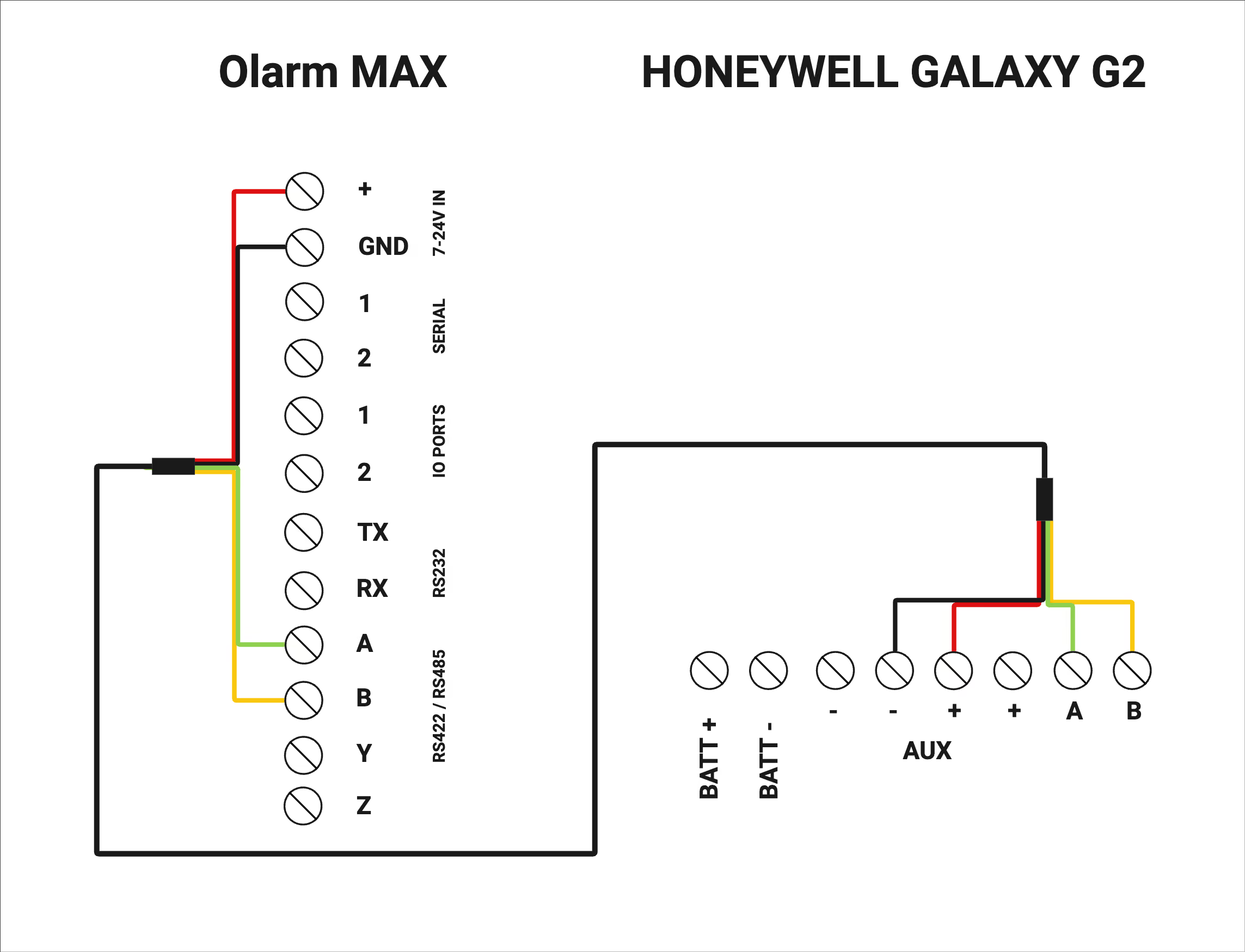
Use one reversible peripheral cable for the RS485 run. Keep the total distance between the Olarm MAX and the panel under 3 metres.
Olarm MAX (Positive +) to the G2 (AUX +) header
Olarm MAX (GND) to the G2 (Negative -) header
Olarm MAX RS485(A) to the G2 (A) RS485 Line 1 header
Olarm MAX RS485 (B) to the G2 (B) RS485 Line 1 header
Programme the Honeywell Galaxy G2
Ensure that the Olarm MAX is wired to the alarm panel before programming.
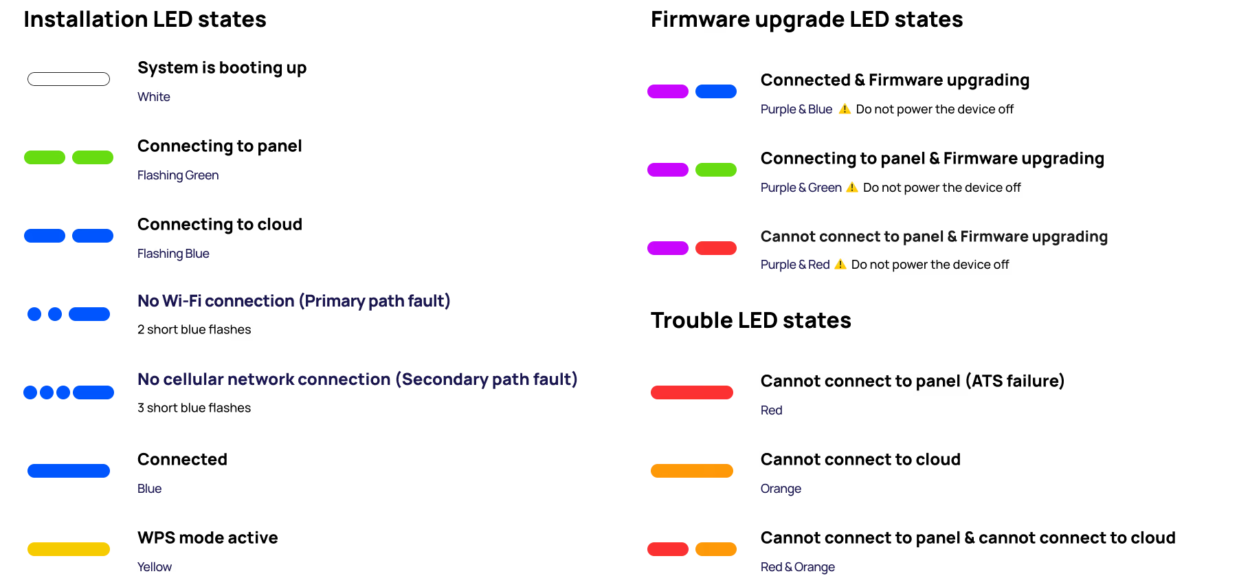
LED States of your device
Power up your Alarm System and Olarm MAX while making reference to the table below for an understanding of the device’s LED states:
Connect the Olarm MAX to the Olarm APP
To complete the installation & to gain app control. The Olarm MAX needs to be added Olarm APP and the prompts need to be followed for successful installation.
There are two methods to add the device to the app. Follow the steps below:
Method 1: Scan the QR Code
In the Olarm APP, tap on “Add Device”
Select “Open Camera”
You will find the unique QR code on the back of the device beneath the internal power supply compartment.
.png)
Method 2: Manually enter the device serial number & verification code
In the Olarm APP, tap on “Add Device”
Select “Enter Serial”
You will find the unique serial number on the back of the device beneath the internal power supply compartment. Enter the serial number in the Olarm APP.
Enter the “V.Code” also found on the back of the device below the serial number and follow the prompts.
.png)
Name the Olarm device & select the country the device is located
Olarm MAX devices are usually named after what or where you are using the system? eg. My Home or 21 Juniper Street
Selecting the correct country of where the device is situated will ensure your Olarm APP displays the correct times for alarm activity.
Select “Next” to proceed
.png)
Connected to a security system
Select “Yes” given your Olarm MAX is connected to an alarm system. Then press “Continue”
.png)
Enter the Master Code
You will be prompted to enter your alarm system's Master Code. This allows this Olarm MAX to connect to your system for app control and monitoring. A vital step in the installation process.
.png)
Connect the Olarm MAX to Wi-Fi
After entering in your relevant code, the app will prompt you to connect the Olarm MAX to Wi-Fi for an enhanced app experience and reliability.
You will need to enter the Wi-Fi networks password, should you not have access to the password, see the alternative method to connect it to Wi-Fi.
Connecting your device to Wi-Fi is highly recommended by Olarm.
.png)
Alternative method to connect it to Wi-Fi.
Press the “FN” button found on the back of the Olarm MAX near the screw terminals
- This will put the device in WPS Mode for around 3 minutes
- On the WiFi router of the network you are wanting to connect to, press the WPS button
- The Olarm MAX will automatically pair with the WiFi network
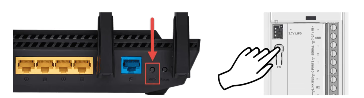
Note: The Olarm MAX only supports 2.4GHz Wi-Fi
Setting up remote programming via RSS
Olarm REMOTE CONNECT lets a technician use Honeywell RSS to service a panel remotely, without being on site. The Olarm MAX takes the place of the panel's Ethernet module, and the connection between RSS and the panel is carried securely through the Olarm Cloud.
.png)
Requirements for remote programming
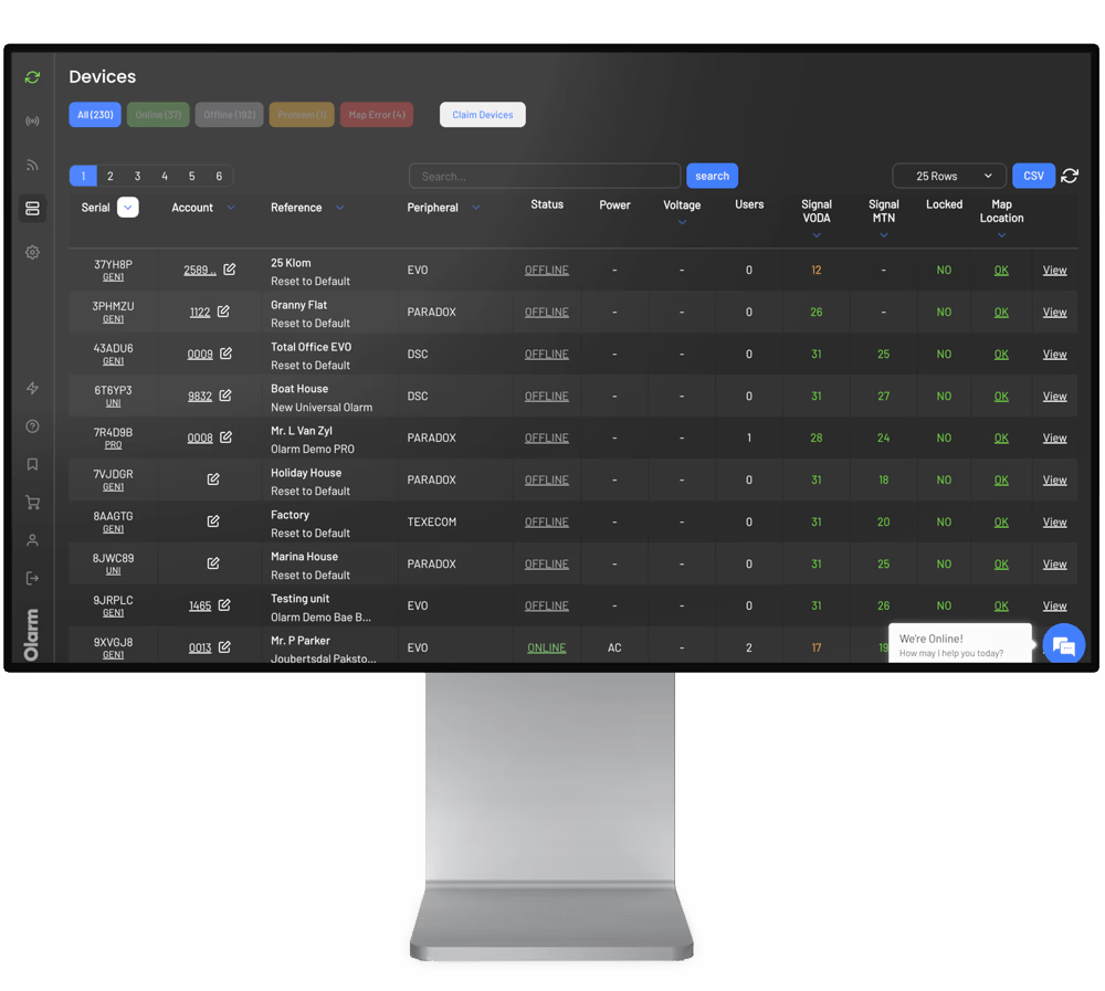
- Olarm COMMAND CENTRE
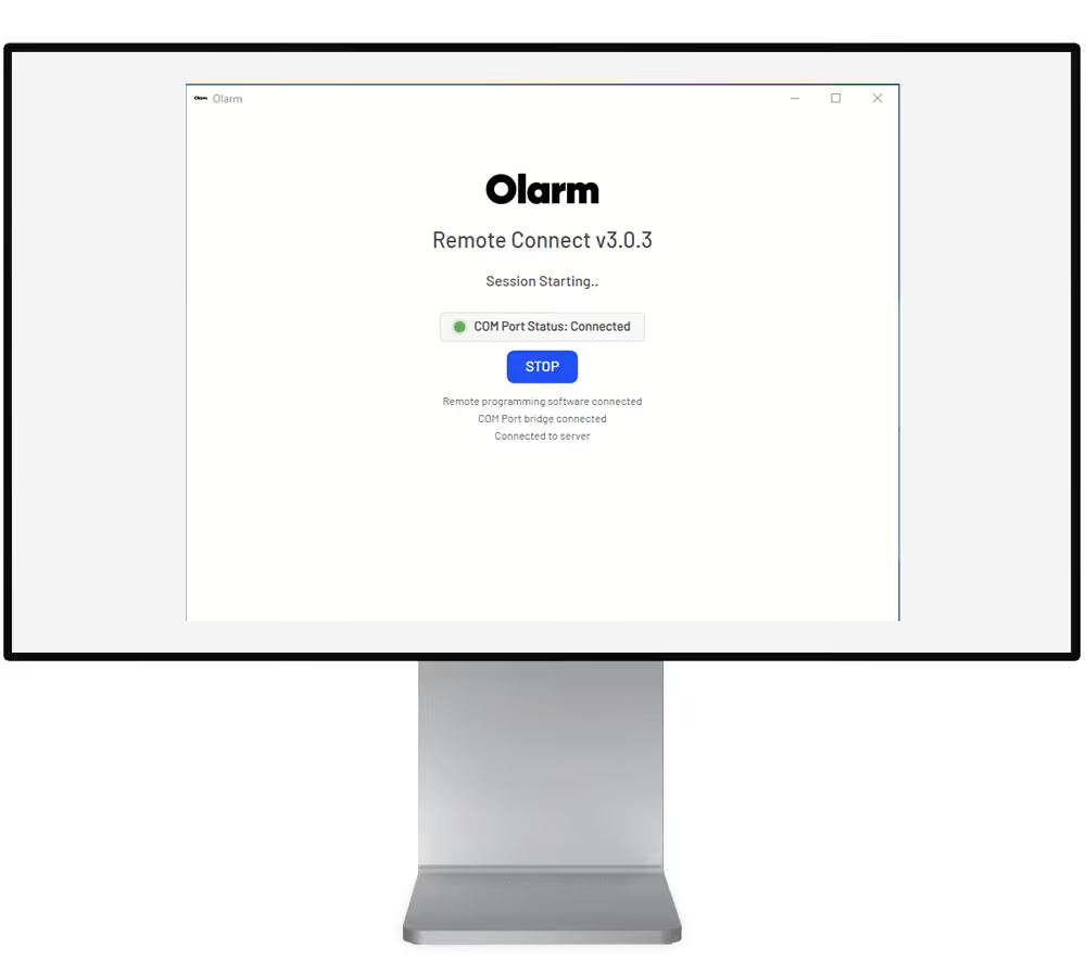
- Olarm REMOTE CONNECT
- Honeywell Remote Servicing Suite
Tip: Ensure the Olarm MAX on-site is connected to Wi-Fi for optimal remote programming experience.
Establish the virtual connection to the Olarm MAX
In Olarm COMMAND CENTRE:
- Navigate to the Olarm MAX connected to the site you wish to remotely programme.
- Select the tab "Remote Programming"
- Click on Generate & Copy the key to paste into Olarm REMOTE CONNECT
Then open Olarm REMOTE CONNECT:
- Paste the key copied from Olarm COMMAND CENTRE
- Select Connect to establish the a local remote session to the Olarm MAX

Add new site (if site not added in RSS)
Open your Frontshell & Commserver
- In the RSS software, navigate to the Site tab
- Select Add new site
- Load the following details as required:
- Site Location
- RRI Report Address
- User Defined Fields
- For Remote Servicing Information set the following for the Olarm MAX remote programming functionality:
- Remote address set to "127.0.0.1"
- Remote port set to "9977"
- Drop down the panel type & select "Galaxy 2 Series"
- Enter the Central Station ID
- This is the panels unique Downloader ID
- Found in engineering menu (56.1.12.4) - 56(Communications). 1(Telecoms). 12(Remote Access). 4(Downloader ID)
- The panel default Downloader ID is set to "99999999"
- Select Finish once other details have been filled in.

Establish the remote session to the panel
Open the site you wish to remotely programme:
- In the Grade 2 Application page, navigate to the Setup tab
- Select Ethernet as the connection type
- Ensure Encryption is disabled
- Press OK & proceed to Dial to establish the remote session via Olarm REMOTE CONNECT
- Success message will appear

Not able to establish a connection?
Check the following:
- Ensure Encryption is disabled in the CommServer's Communication Configuration
- Ensure the panel's Downloader ID matches the 8 digits entered in RSS
- Ensure your firewall is not blocking any traffic on the local port 9977
- Ensure the Olarm MAX is able to control the panel via the Olarm APP with the correct Master Code entered in-app
- The System ID, if programmed on the panel is required in RSS. By default it is left blank.
- Olarm REMOTE CONNECT needs to be on the same PC you are running Honeywell RSS. Or a Virtual Machine alternative.
Troubleshooting LED states of Olarm MAX
Red
Check the connection between your Olarm MAX and the alarm system which includes wiring, programming and entering the UDL/Master code in the Olarm APP.
Orange
Ensure your Olarm MAX is installed in an area with adequate signal strength. Alternatively, connect the device to Wi-Fi through its WPS capability.
Red & orange
Troubleshoot everything mentioned above.
Three blue flashes
Relocate the device to an area with better GSM/LTE signal strength. Alternatively, ensure there are no other peripherals nearby that could be interfering with the devices connectivity.
Two blue flashes
The Olarm MAX has lost Wi-Fi connectivity. Connect the device to Wi-Fi through one of the two methods. Ensure your device is in-range of the Wi-Fi network.
Mounting the Olarm MAX
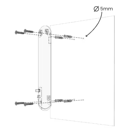
Follow the diagrams below to mount the Olarm MAX.
Using the screws and wall plugs provided, mount the backplate to the flat surface as shown in the diagram below.
Place the Olarm MAX flat against the mounted backplate and slide the enclosure down to click into place
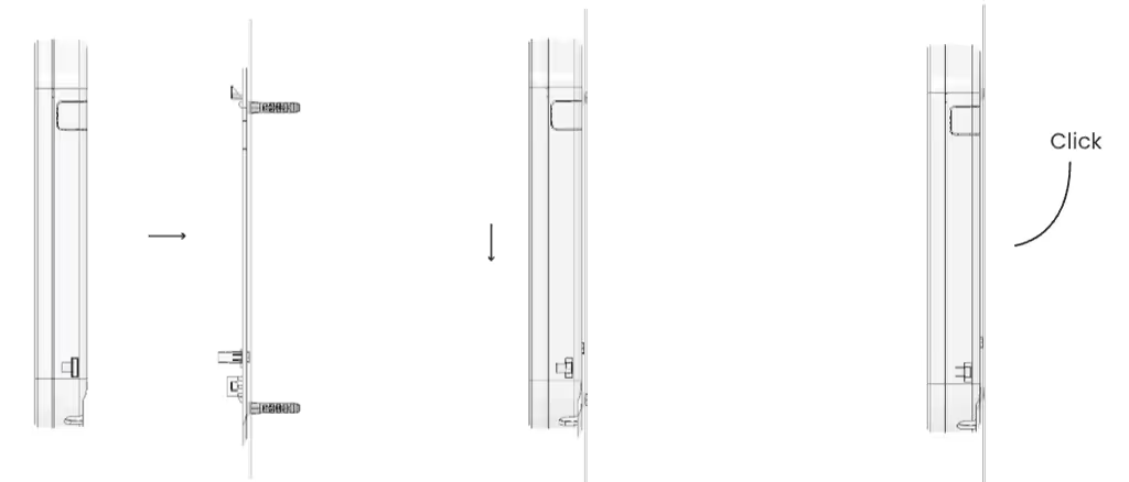
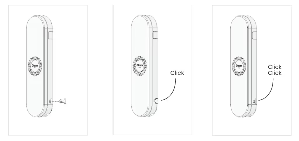
Using the locking key, apply force to insert the mechanism into the key hole until flat against the enclosure, which is indicated by two clicks.
Note
- Do not mount the Olarm MAX inside or against the alarm system enclosure, as this will hinder its connectivity capabilities.
- Do not mount the Olarm MAX near any other communication equipment, as they will inter with each others abilities to transmit signals.
- Utilise a non-metal enclosure should you mount the Olarm MAX outdoors.
- The maximum distance between Olarm MAX and Alarm System is 3 meters.
Troubleshooting
Olarm MAX LED is flashing green and blue, not connecting to the alarm panel?
This behaviour can lead to panel instability and communication errors reported to the control room.
Steps to resolve:
- Disconnect the Olarm MAX, including the super capacitor (allow the Olarm MAX to turn off)
- On the DSC NEO panel, go to location 380 and disable Comms.
- Go to location 382 and disable Alternative Comms.
- Restart the DSC NEO panel.
- After the panel restarts, go back to:
- Location 380 and enable Comms
- Location 382 and enable Alternative Comms
- Reconnect the Olarm MAX, including the super capacitor.
Need help? Contact our support team