


.png)
Step 1
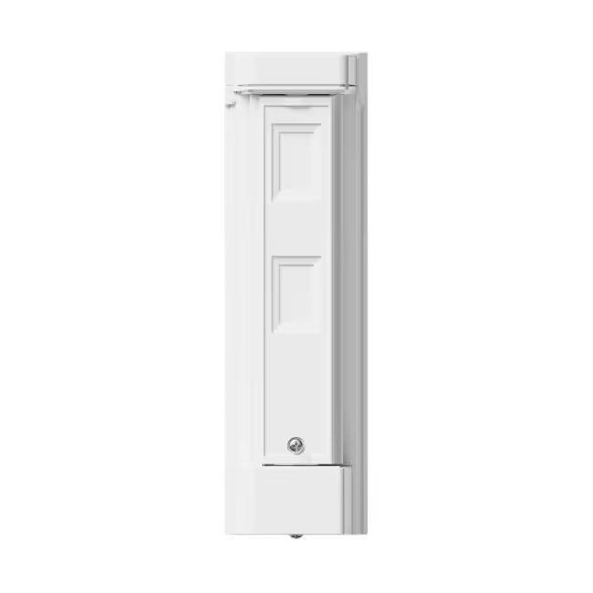
Remove the front lid
Use a flathead screwdriver to lift, leverage upwards & release the lid.

Step 2
Insert the battery
Insert the the provided CR123A battery to power up the Olarm ENTRY. Ensure the battery orientation matches the symbols enclosure.

Add your device
Scan the QR code on the Olarm ENTRY, then configure the zone & detector settings.
Step 3
Control a gate, garage or strike lock
Olarm ENTRY can be used to open and close various security peripherals such as gates, garages, strike locks and more. Follow the steps below for guidance.
Step 3.1
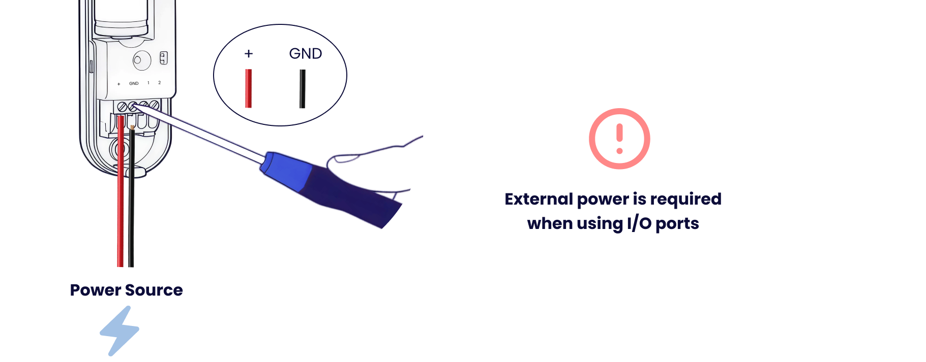
Connect external power (5-30V DC)
External power is required when using the I/O Ports. The peripheral you are wanting to control may have a power source. Ensure this is between 5 - 30V.
Step 3.2
Wire the I/O Ports as required
Ensure the peripheral you are wiring the Olarm ENTRY to provides a ground/common reference. This is mandatory for installation.

Step 3.3
Installing on gate motor
Gate motor's provide a power output of 12-24V for the Olarm ENTRY. Ensure a ground/common reference is wired between the device and the gate. Gate motors have different dedicated terminals for triggering an open/close.
.png)
Step 3.4
Installing on garage motor
Garage motor's provide a power output of 12-24V for the Olarm ENTRY. Ensure a ground/common reference is wired between the device and the garage. Garage motors have different dedicated terminals for triggering an open/close.

Step 4
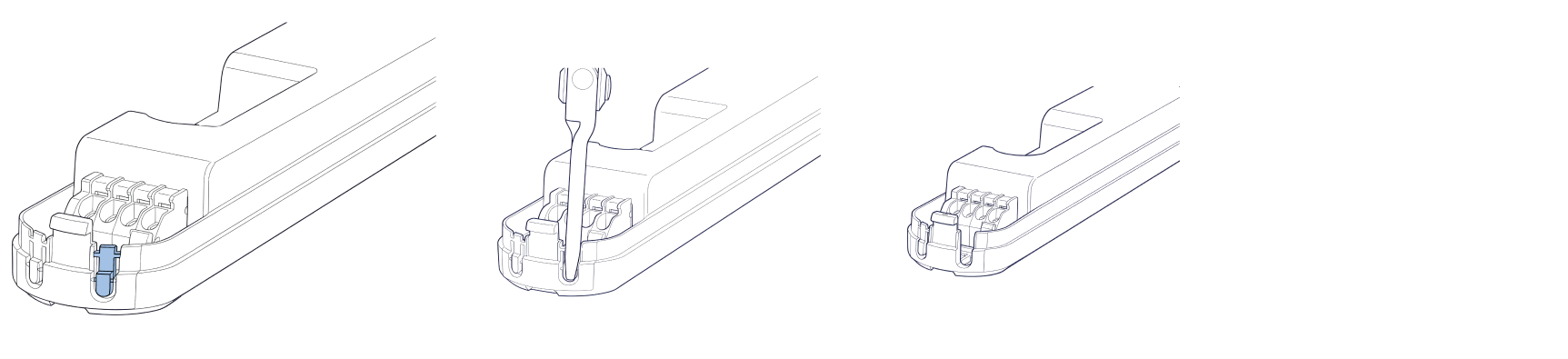
Snap off the breakouts to feed cables
Using pliers, snap off the cable running breakouts and feed cables through for a neat looking installation.
Step 5 (optional)
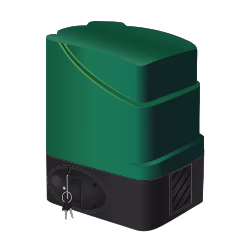
Secure the main unit
Secure the Olarm ENTRY in a water resistant enclosure to ensure the device's longevitiy. Where possible, use the provided mounting hardware to secure the device to a surface.

Step 6
Close the front cover
Close the front cover of the Olarm ENTRY, ensuring the device is properly sealed. Store in a weather-proof area.
.png)
Step 7
Setup the I/O Ports in-app
Navigate to the Olarm ENTRY in your device list and press settings. Then navigate to I/O Ports and configure for controlling/monitoring your relevant peripheral. See GIF below for guidance.
Step 8
Test I/O Port behaviour
Try out the newly added I/O Port control or monitoring of the connected peripheral.
Step 9
LED States
Understand what each LED pattern means on your Olarm ENTRY.
